Case Study V
Container Ship
Recurring Failure of Side Longitudinal Passing through a Web Frame
Quick Link Index:
Vessel Particulars
Length: (LBP) 810.00'
Beam: 105.75'
Depth: 66.00'
Designed Draft: 29.00'
Scantling Draft: 35.00'
Shipyard: U.S.
Class: ABS
Date Built: 1980
Vessel Type: Container Ship
Framing Convention: Longitudinally framed from hold 1 through hold 6; transitioning to transverse framing at ends
Arrangement: Accommodations forward and machinery three-quarters aft. Four holds (9 container bays) forward of and two holds (4 container bays) aft of the machinery space.
Hull Material: XH-36 high strength steel throughout (longitudinal and transverse material)
Arrangement and Construction Details:
From hold 1 through hold 6, including the machinery space, the double bottoms are used for saltwater ballast. Throughout this same length wing tanks, extending from the tank top up to the underside of the longitudinal box girder or second deck, are dedicated to either fuel oil or saltwater ballast.
In the longitudinally framed portion of the hull (from hold 1 through hold 6) the web frame spacing is 11.00'. The longitudinals are spaced 33" apart in the wing tanks and consist of angles and channels cut to angles. Beginning below the box girder the shell and bulkhead longitudinals increase in size from 6" x 4" x 3/8" to 8" x 6" x 1/2" angles before switching to 13" x 4" x 35# cut channel, as shown in Figure 1.
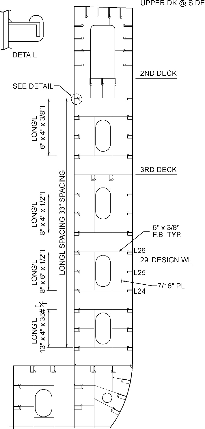 Figure 1. Wing Tank Longitudinal Stiffeners
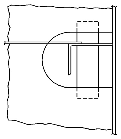
For convenience during construction the web frame cutouts for longitudinals were made clear all around as shown in Figure 2 instead of the more normal type of cutout detail indicated in Figure 1.
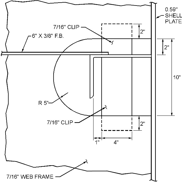 Figure 2. Original Cutout Detail for L24 to L26, 8" x 6" x 1/2" Longitudinals
The longitudinal bulkhead which forms the inner boundary of the wing tanks follows the approximate slope of the outer shell as the ship lines fine up in the forward portion of the cargo space. The resulting wing tanks are sloped, narrow and are very difficult to access for inspection.
Back to Quick Link Index
Summary of Structural Failure
Progressive failure occured beginning with the fracture of a web frame flat bar stiffener attachment to the longitudinal, buckling of clips between the web frame and longitudinal, fracture of the longitudinal, fracture of the longitudinal weld to the shell and finally fracture of the shell leading to a fuel oil leak. In some instances a similar fracture occurred in the longitudinal bulkhead.
Back to Quick Link Index
Background
The ships in question (a class of three) were in regular transpacific service and operated at an essentially constant draft East and West bound.
The fractures have been common on all three ships of the class. Because they occur in fuel oil tanks that are not subject to frequent interior inspection, the failures are first discovered when a sheen or oil is seen on the water around the forward end of the ship or when a fuel oil leak is visually detected in the cargo holds.
The cause of these failures is poor detail design, incorporating the large open cutout for the longitudinals and the highly eccentric 8" x 6" angle longitudinals, in an area of the ship subject to repetitive impact loading from waves. Figure 2 illustrates how the longitudinal is not adequately supported.
Back to Quick Link Index
Detailed Description of Structural Failure
After detecting a fuel oil leak, the fuel oil tank in question was emptied, cleaned and gas freed to allow inspection and subsequent repair.
Most of these failures begin when the web frame flat bar stiffener on one of the shell longitudinals, L24 through L26, fractured at the longitudinal or the lap weld of the stiffener to the longitudinal. With the stiffener no longer providing support all of the loading on this "wind and weather" strake longitudinal is transferred to the web frame through the poorly proportioned clips on the 8" x 6" angle. The clips buckle under the load. The buckled clips combined with the 10" of unsupported shell in way of the web frame cutout allow the longitudinal to flex in bending and torsion at what should be a rigid support at the web frame. This lack of support combined with the large web frame spacing and the load induced twist in the eccentric 8" x 6" angle raises the stress level in the longitudinal causing it to fracture about 12" from the web frame at a drain hole in the angle. After the longitudinal fractures, a fracture forms in the weld of the longitudinal to the shell plating that travels a short distance back toward the web frame. As this fracture lengthens toward the web frame the stress in the shell plating increases and, when combined with the elevated shell plating stress in way of the large longitudinal cutout, causes the shell to fracture. The shell fracture is in the form of a small half moon centered over the longitudinal's web near the edge of the cutout. Fuel oil then leaks from this half moon shell fracture.
It is believed that the initial web frame flat bar stiffener and weld fractures occur because the angle type longitudinals twist as they bend under the load of wave impacts on the shell. This twist is exaggerated in an angle with eccentric proportions of 8" x 6". The twist puts a torsion load on the connection of the longitudinal to the web frame. For this detail the connection consists of only the flat bar stiffener and the two poorly proportioned clips. Such a connection does not resist torsion loads well leading to fatigue failure of the weakest link, the 6" x 3/8" flat bar stiffener or its weld.
The same pattern of failure occurred over a period of years but was always confined to longitudinals L24 through L26, the 8" x 6" angles. The failures occurred in the four forward wing tanks although most were in the forward most tank where the "wind and weather" loads were the greatest. There were also instances where these failures occurred on the longitudinal bulkhead in way of the 8" x 6" longitudinals leading to fuel oil leaks into the cargo holds.
Back to Quick Link Index
End Result
For many years the damaged shell (or longitudinal bulkhead) plating was removed and inserted, a section of the 8" x 6" longitudinal was replaced extending forward and aft of the web frame, the clips were repaired or replaced and the flat bar stiffener was repaired, inserted or replaced. But, no changes were ever made to the design detail or to the scantlings.
When the ships were taken over by a new owner, he decided to tackle this persistent problem. The wing tanks were visually inspected where various stages of the failure could be observed. The failure scenario above was developed from these observations. Based on the failure scenario a design modification was developed and turned into a drydock repair specification. After making repairs to and/or replacements of damaged material and welding the following modifications were carried out.
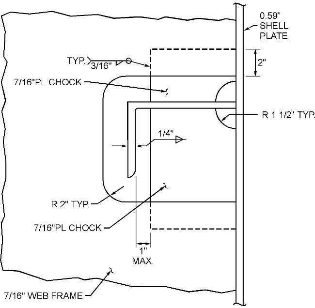 Figure 3. Modified Cutout Detail for L24 to L26, 8" x 6" x 1/2" Longitudinals
The original clips attaching each longitudinal to the web frames were replaced with larger chocks, which were fitted against the shell plating. The modified chocks are shown in Figure 3. These chocks provide more weld attachment of the longitudinal to the web frame, provide a torsionally stiff end condition for the longitudinal, and provide support for the shell plating across the gap of the large cutout. New brackets were also added between the web frames and the longitudinals as shown in Figure 4. These chocks are aligned with the existing flat bar stiffeners on the opposite side of the web frame and provide additional support for the longitudinal and reduce the stress in the flat bar where it attaches to the longitudinal and where this type of failure begins.
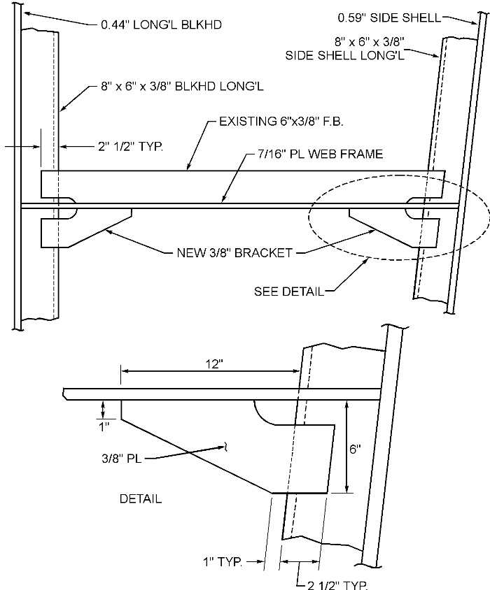 Figure 4. Plan View of Modified Web Frame Stiffener Bracket
These modifications were carried out at the new owner's first drydocking in the forward three fuel oil wing tanks in way of the 8" x 6" longitudinals, L24 to L26. The same modifications will be carried out in other wing tanks at future drydockings as those tanks are opened up for inspection.
Back to Quick Link Index
Acknowledgements
Author:
William A. Wood, Seaworthy Systems, Inc., 800 Cooper Road, Voorhees, NJ 08047
Mr. Wood is the chief Naval Architect and a Vice President of Seaworthy. He has over 30 years of experience in ship design, structural analysis, failure investigation, shipbuilding and ship repair.
Back to Quick Link Index
Back To SSC
Structural Failure Home Page
This web site was developed by:
JMS Naval Architects & Salvage Engineers
| 
 Monday,
07/07/2025
Monday,
07/07/2025